variable bandwidth filter
The Variable Bandwidth IIR Filter block filters each channel of the input signal over time using specified IIR filter specifications. The core aperture widths of.

State Variable Filter An Overview Sciencedirect Topics
A variable bandwidth VBW filter whose bandwidth can be varied dynamically is implemented using Farrow structure.

. The field effect transistor is shunted by a capacitor and the gate of the field effect transistor is fed with a control voltage via a feed-back. This is done by comparing the requirements of the analog-to-digital converter with and without an analog filter with a variable bandwidth. A variable bandwidth filter comprises a transistor long-tailed pair.
Conventionally an ideal filter is unsuitable for studying a real filters performance. Solution A radio reception circuit 1 comprises. A variable bandpass filter 2 for passing one of received signals that has a particular frequency and that is of a particular bandwidth.
The filter is tuned. A variable bandwidth filter is fabricated by changing the core aperture width as shown in Fig. Many signal processing applications require digital filters with variable frequency characteristics especially the filters with variable bandwidth and center frequency.
Variable bandwidth birefringent filter for tunable femtosecond lasers. All the required bandwidths for the set of selected audiograms are derived from the VBW filter. A better option would be a smooth Butterworth response with minimum ringing at a fixed frequency.
Therefore variable bandwidth filter can be realized by changing the output waveguide core aperture width. The variable bandwidth method of filtering an amplitude modulated signal is proposed to preserve amplitude modulation and enable accurate CFC measurements. A demodulation circuit 3 for demodulating the received signal having passed through the variable bandpass filter thereby outputting an ultimate output signal.
This block offers tunable filter design parameters which enable you to tune the filter characteristics while the simulation is running. The bandwidth can be continuously changed using varicap diodes. In addition we show that there exists a bandwidth tuning range over which the filter exhibits no extra insertion loss and no degradation in the filter shape.
The Variable Bandwidth FIR Filter block filters each channel of the input signal over time using specified FIR filter specifications. Due to their linear phase and inherent stability finite impulse response FIR filters are the popular choice in the majority of the applications. The Variable Bandwidth FIR Filter block filters each channel of the input signal over time using specified FIR filter specifications.
Govt MeSH terms Action Potentials physiology Brain physiology Fourier Analysis Humans Models Neurological. Other adaptive-filter-oriented VDFs include notch filters with variable attenuation at the notch frequency comb filters with variable bandwidth and variable attenuation. You can vary the BFO for shifting the audio tone.
A frequency characteristic table. The studies cited in the previous paragraph all used ideal. One of the transistors of the pair has a field effect transistor which is connected in the collector circuit of the transistor and which is used as a variable collector load resistor.
The block designs the FIR filter according to the filter parameters set in. 95 is almost constant in 155 μm region. This transceiver has a quartz filter of variable bandwidth.
Karl-Heinz was impressed by the acoustic result of the simple circuitry of his HB-1B and wondered why this alternative had not previously been used. 3 rows The variable bandwidth filter detects amplitude modulation across all modulation frequencies. Simple but very effective.
Filter module PCB ready-built. The variable bandwidth IIR filter is designed using the elliptical method. As described the variable bandwidth filter operates in such a way that a signal tuned on the nose remains in the center of the filter regardless of the bandwidth setting.
The Variable Bandwidth IIR Filter block filters each channel of the input signal over time using specified. Store your favourite setting as a power-up default. The proposed variable bandwidth.
This block offers tunable filter design parameters which enable you to tune the filter characteristics while the simulation is running. A passive variable bandwidth memristor-based Legendre-Optimum L-Opt LPF for use in the RF band is presented in this work. The circuit diagram of the HB-1B can be found here.
A 400 hz bandwidth will be narrow enough and yet offer a brightness that we miss in more aggressive designs. This block brings the capabilities of dspVariableBandwidthIIRFilter System object to the Simulink. The filters are continuously variable and always have near perfect characteristics unattainable with conventional analogue techniques.
The usual method to change the frequency response of a digital filter is to increase the number of taps or the order of the finite impulse response FIR filter to reduce the bandwidth and to decrease the number of taps to increase the bandwidth. Variable Bandwidth IIR Filter Description. All of these variable notch filters successfully provide the variable characteristics by simple mechanism without delay-free loops or increase of computational cost.
Publication types Research Support NIH Extramural Research Support Non-US. The focused beam movement per unit wavelength at output slabarray interface which is given by Eq. These filters are then tuned separately to the optimum center frequencies and bandwidths to match each of the audiogram.
7 rows y vbwx filters the input signal x using the variable bandwidth FIR filter to produce the. Several methods exist 1-8 for realizing the discretely variable bandwidth filter. It means that the filter will exhibit ringing and phase delays.
The filters ripple-free passband and steep roll-off make it desirable. Then a technique for channel filtering is described in which two passive filters are. Then the advantage of analog channel filtering with a variable bandwidth in a Software Defined Radio is demonstrated.
We demonstrated a 4 th-order variable bandwidth filter in Silicon-on-Insulator achieving a bandwidth tuning range from 03 nm to 135 nm with a maximum in-band ripple of 3 dB. Click to switch between variable bandwidth or centre frequency. If this feature can be dispensed with considerable simplification of the device is possible.
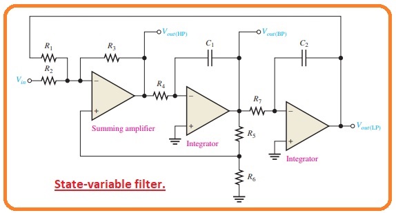
State Variable Filters

Sallen And Key Filter Design For Second Order Rc Filters
Filter Bandwidth An Overview Sciencedirect Topics
Filter Basics Stop Block And Roll Off Nuts Volts Magazine
Active Band Pass Filters Selection Guide Types Features Applications Engineering360

State Variable Filter Design Electronics Tutorials
Types Of Active Band Pass Filters The Engineering Knowledge
How To Build Audio Filter Circuits Circuit Basics

Band Stop Filters Are Called Reject Filters
How To Build Audio Filter Circuits Circuit Basics

Second Order Filters Second Order Low Pass Filter

Notch Filters An Overview Sciencedirect Topics
State Variable Filters

Butterworth Filter First Order And Second Order Low Pass Butterworth Filter Butterworth Gps Tracking Device Digital Circuit
State Variable Filters
Active Band Pass Filters Selection Guide Types Features Applications Engineering360

Audio Eq What Is A Low Pass Filter How Do Lpfs Work My New Microphone

Sallen And Key Filter Design For Second Order Rc Filters
Types Of Active Band Pass Filters The Engineering Knowledge


Comments
Post a Comment